 Download:
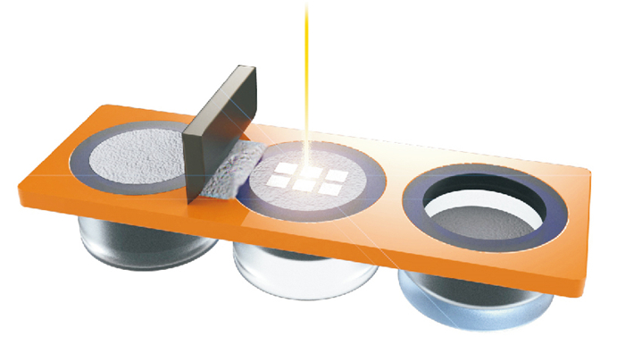
SLM technology working platform diagram
Figures of the Article
-
![]() SLM technology model slicing process diagram: a.Schematic diagram of slicing principle; b.Slice section diagram; c.Model diagram after slicing
SLM technology model slicing process diagram: a.Schematic diagram of slicing principle; b.Slice section diagram; c.Model diagram after slicing
-
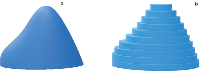
![]() Stereomodel and post-slice print model before slicing (a) and after slicing (b)
Stereomodel and post-slice print model before slicing (a) and after slicing (b)
-
![]() SLM technology working platform diagram
SLM technology working platform diagram
-
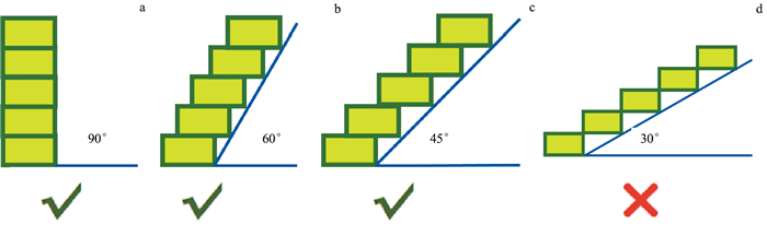
![]() Schematic diagram of angle limitation of SLM technology
Schematic diagram of angle limitation of SLM technology
-
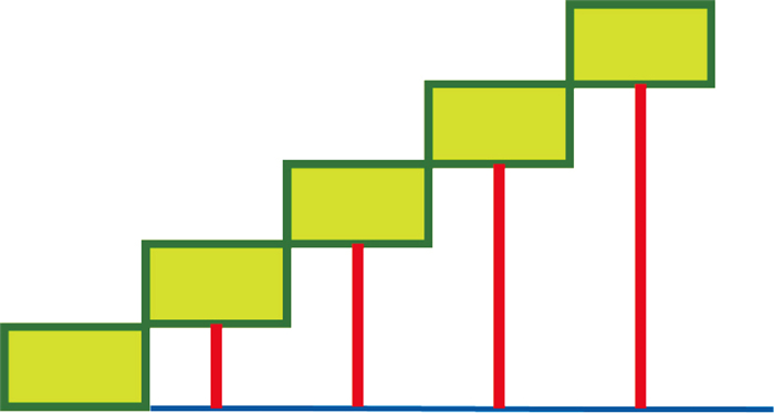
![]() Schematic diagram of supporting structure for 30 degree angle of model
Schematic diagram of supporting structure for 30 degree angle of model
-
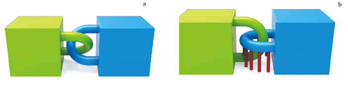
![]() Connection structure requiring support and optimization scheme: Ring structure requiring support (a) and optimized ring structure (b)
Connection structure requiring support and optimization scheme: Ring structure requiring support (a) and optimized ring structure (b)
-
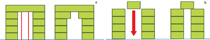
![]() Span design that needs supporting structures and optimization scheme: Arch-like structure (a) and reduction of suspended span (b)
Span design that needs supporting structures and optimization scheme: Arch-like structure (a) and reduction of suspended span (b)
-
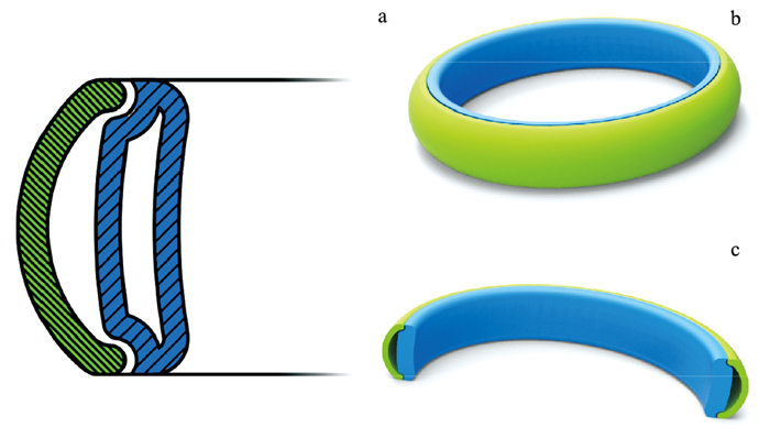
![]() Schematic diagram of bearing slidable structure longitudinal section view (a), model perspective view (b) and perspective sectional view (c)
Schematic diagram of bearing slidable structure longitudinal section view (a), model perspective view (b) and perspective sectional view (c)
-
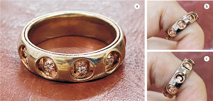
![]() Finished product of bearing slidable structure ring (a), before turning (b) and after turning (c)
Finished product of bearing slidable structure ring (a), before turning (b) and after turning (c)
-
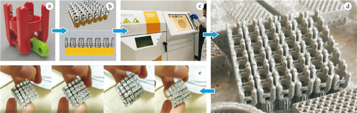
![]() Axis movable structure jewelry design flow chart: a.Axis active structure modeling unit diagram; b.Axis active structure combination effect diagram; c.SLM metal printing; d.Finished pieces; e.Finished product
Axis movable structure jewelry design flow chart: a.Axis active structure modeling unit diagram; b.Axis active structure combination effect diagram; c.SLM metal printing; d.Finished pieces; e.Finished product
-
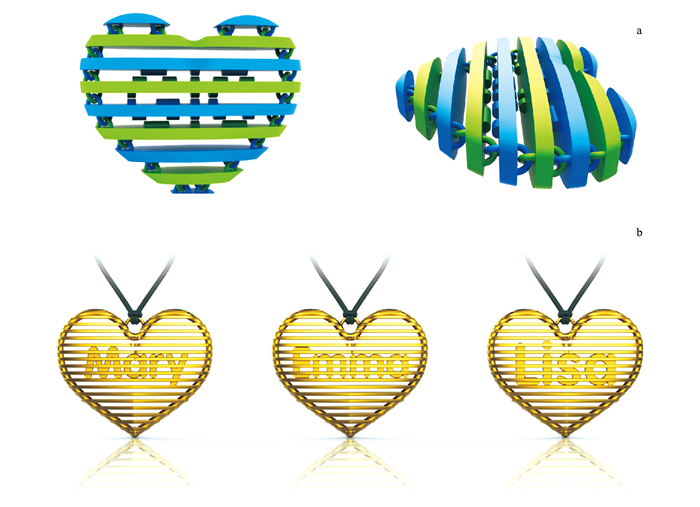
![]() Stereogram model of louver movable structure (a) and rendering of print (b)
Stereogram model of louver movable structure (a) and rendering of print (b)